L293D馬達驅動板
The shield contains two L293D motor drivers and one 74HC595 shift register. The shift register expands 3 pins of the Arduino to 8 pins to control the direction for the motor drivers. The output enable of the L293D is directly connected to PWM outputs of the Arduino.
The Motor Shield is able to drive 2 servo motors, and has 8 half-bridge outputs for 2 stepper motors or 4 full H-bridge motor outputs or 8 half-bridge drivers, or a combination.
模組板規格
- 2 connections for 5V 'hobby' servos connected to the Arduino's high-resolution dedicated timer - no jitter!
- 4 H-Bridges: L293D chipset provides 0.6A per bridge (1.2A peak) with thermal shutdown protection, internal kickback protection diodes. Can run motors on 4.5VDC to 25VDC.
- Up to 4 bi-directional DC motors with individual 8-bit speed selection (so, about 0.5% resolution)
- Up to 2 stepper motors (unipolar or bipolar) with single coil, double coil or interleaved stepping.
- Pull down resistors keep motors disabled during power-up
- Big terminal block connectors to easily hook up wires (18-26AWG) and power
- Arduino reset button brought up top
- 2-pin terminal block and jumper to connect external power, for separate logic/motor supplies
- Tested compatible with Arduino Mega 1280 & 2560, Diecimila, Duemilanove, and UNO
- Download the easy-to-use Arduino software library, check out the examples and you're ready to go!
http://www.kidmakers.org/-for-the-galileo/
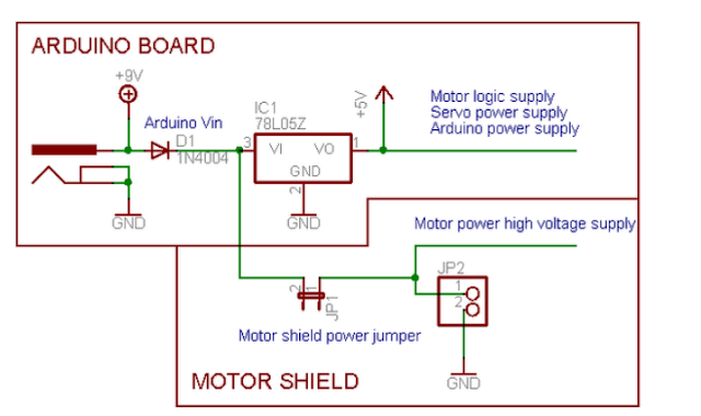
Motor shield Motor電源與Arduino Vin 關係
L293D 線路
L293D 控制原理
- Vcc1/Vss--> 提供L293D chip的電源 5V
- Vcc2/Vs --> 提供馬達電源 (max 36V); 從Arduino Vin 接入 (PWR jumper接上)或是motor shield的EXT_PWR接入 (PWR jumper要移除)
- Enable1,2 及Enable3,4是致能訊號, 可以直接Vcc1; 也可以接到PWM訊號,給Enable1,2, 不同duty cycle,即提供馬達不同的功率, 使得馬達有不同轉速。Enable1,2接上Vcc1, 即duty cycle為100%,此為全速運轉
- Output1及Output2接DC Motor 的兩隻腳
- Input1, Input2 是控制DC Motor輸入訊號, 接到2個GPIO用以控制順、逆、停動作, 為<1,0>或<0,1>, <0,0>
- 控制4個DC Motor則需要4個PWM 來控制4顆達轉速及8個GPIO 來控制4顆馬達方向
- 1,2 Enable, 3,4 Enable 都使用,就是 full H-bridge

2) 直流馬達的 PWM 調速控制原理


請問如何透過raspberry Pi 3直接控制這塊板子,是直接透過寫GPIO還是網路上有寫好的library可以拿來用?
回覆刪除另外就是是否有這兩個板子連接的電路圖可供參考?謝謝。