2016年12月30日 星期五

Wi-Fi 與Zigbee 的MAC Algorithm


Zigbee 的MAC Algorithm:

(1) Binary Random Backoff
(2) Channel Idle > CCA (CW=2)  ==>  如果CW減到0 則傳送否則重新再來過

CW=2 是一個固定值 , 表示idle 至少有CW以上的時間,才認為channel idle 才可以傳

若Binary Random Backoff 完後, channel仍不是idle (包含CW沒有減到0) 則再一次進行Binary Random Backoff

BP=random(0, 2^BE-1)

BP: Backoff Period
BE: Binary Exponent , 每次發生collision .  BE都會增加 ,其初始值為3, 則第一次BP為random(0,7)
NB: backoff 次數限值


Wi-Fi 的MAC  Algorithm (DCF)

DCF (Distributed Coordination Function)= CSMA/CA+ACK

程序:

(1) Channel Idle > DIFS  ? ==>  channel idle是否大於DIFS的期間,若否繼續偵側,直到大於DIFS。若大於DIFS, 則隨機選一個random backoff window, 並且每一個time slot減1, 當減到0時, 才能傳送。減1的動作只有在判斷channel 是Idle的狀態才會減1, 若channel是busy狀態, 則不減1 ("freeze Backoff window")

採用time backoff 機制讓其他人有機會可以取得medium來傳送。

(2) Binary Random Backoff ( 決定了CW的值 ) =>  當CW減到0時, 就直接傳送不用管channel idle與否。若傳了之後是發生碰撞(沒有收到ACK則視為碰撞),則此次傳輸沒有成功, 再重傳, 從(1)再來過。

CW=2 非固定值,  CW=random(CWmin, 2^BE-1) 介於CWmin~CWmax中間,

CWmin------------ CW-------------------CWmax
CW=min(CWmax, CW)
CW=max(CWmin, CW)

若idle 長度至少有DIFS的長度才視為channel idle


----------------------------------------------------------

Wi-Fi vs  Zigbee 


  • Zigbee和Wi-Fi 都是利用 Time Backoff 來創造一個公平機會的Medium Access 機制 
  • Zigbee 的CW是固定值, 而Wi-Fi CW是一個變數, Wi-Fi CW 其實是Zigbee 的BP, 兩者名稱相同, 但意思不同
  • Zigbee 評估 Channel Idle , 看CW, 而Wi-Fi 評估 Channel Idle , 看DIFS
  • Zigbee Backoff 的 BP會一直減1不管channel 是否idel或有人傳 , 而Wi-Fi Backoff 的 CW會減1但必須channel 是 idel狀態才能減1


CCA: Clear  Channel Assessment

CW: Contention Window

DCF: Distributed Coordination Function

DIFS: DCF Inter Frame Space


 References:

  1. https://www.vocal.com/networking/802-11-distributed-coordination-function-dcf/
99.9% of the time Wireless is half duplex. There are experiments that can result in a "full duplex" wireless network but that's all lab-based and not real-world.
Full-duplex is what most wired connections use which means two devices can send and receive data at the same time and can also detect collisions straight away. via CSMA/CD
With Wireless the devices cannot send and receive simultaneously and they cannot sense collisions. Instead they use CSMA/CA to detect usage on the frequency to see if it is safe to transmit data. There are a large number of factors that can affect a wireless signal and interfere with it which results in lower throughput.


2016年12月23日 星期五

Raspberry Pi SD卡從8G變16G


從8G SD卡變成16G SD 卡, 要如何resize Partition


原本8G:

fdisk -h

Device         Boot  Start      End  Sectors  Size Id Type
/dev/mmcblk0p1        8192   137215   129024   63M  c W95 FAT32 (LBA)
/dev/mmcblk0p2      137216 15564799 15427584  7.4G 83 Linux


首先,您需要使用fdisk更改分割表 要刪除現有的分區條目,然後創建一個新的分區吃滿整個可用空間。


Manually resizing the SD card on Raspberry Pi

You can also resize the partitions of the SD card that your Pi is running on.
First you need to change the partition table with fdisk. You need to remove the existing partition entries and then create a single new partition than takes the whole free space of the disk. This will only change the partition table, not the partitions data on disk. 


The start of the new partition needs to be aligned with the old partition!
Start fdisk:
sudo fdisk /dev/mmcblk0
Then delete partitions with d and create a new with n. You can view the existing table with p.
  • p to see the current start of the main partition
  • d3 to delete the swap partition
  • d2 to delete the main partition
  • n p 2 to create a new primary partition, next you need to enter the start of the old main partition and then the size (enter for complete SD card). The main partition on the Debian image from 2012-04-19 starts at 157696, but the start of your partition might be different. Check the p output!
  • w write the new partition table
Now you need to reboot:
 sudo shutdown -r now
After the reboot you need to resize the filesystem on the partition. The resize2fs command will resize your filesystem to the new size from the changed partition table.
sudo resize2fs /dev/mmcblk0p2
This will take a few minutes, depending on the size and speed of your SD card.
When it is done, you can check the new size with:
df -h

2016年12月11日 星期日

物聯網應用層通訊協定標準比較 CoAP vs MQTT

機器對機器 (Machine-to-Machine, M2M)通訊是物聯網的一個重要運作概念。隨著物聯網的應用日益興盛,M2M流量會持續增加,故針對M2M Traffic特徵及其應用,M2M通訊技術應運而生。由於物聯網架構下,感測節點本身多半採用MCU且以電池供電,故這些新的M2M協定必須考量在有限的硬體能力及功耗等條件下,使得M2M Traffic在進行網路傳輸時,有較高的Throughput、低延遲、低電力耗損,甚至提供不同的 QoS (Quality of Service)。

目前各家提供連結物聯網裝置的雲端資料服務平台,包含
AWS IoT(https://aws.amazon.com/tw/iot/)Evrythng(https://evrythng.com/)、Xively(https://www.xively.com/)、ThingSpeak(https://thingspeak.com/)、ThingWorx(https://www.thingworx.com/)等及晶片廠提供的雲平台,如聯發科的MCS(https://mcs.mediatek.com/)、ARM mbed Device Connector(https://connector.mbed.com/)等,都廣泛支援CoAP及MQTT協定,故將選擇此兩種協定來進行說明與比較。

M2M協定介紹

CoAP


CoAP(The Constrained Application Protocol) 目前已是IETF標準(RFC 7252) ,提出一個類似HTTP/TCP設計,但是屬於輕量版的HTTP/UDP,使得其有利於感測節點進行網路傳輸。

CoAP主要特點:


  1. CoAP同HTTP一樣具有REST(Representational State Transfer)設計風格,也支援GET/PUT/POST/DELETE及URIs的請求方式。
  2. CoAP是主從(Client/Server)架構,感測節點多半為CoAP Client 上傳(PUT)感測資訊或節點狀態到CoAP Server。CoAP Server使用UDP (port: 5683),對於資料是否要重傳或傳送順序(Reordering) 全交由上層應用層來決定,對於資源有限的MCU則不需要TCP協定實作。感測節點多半為CoAP Client, 因為感測節點通常是On-Off (Duty-cycled)工作模式, 只有醒來時才工作以節省能耗。若反過感測節點為CoAP Server, 則由Cloud 作為CoAP Client , 執行Get 以存取節點狀態資訊。
  3. CoAP採用二進位整數格式且封包標頭4 個byte而非HTTP使用字串格式(ASCII code),所以封包傳送時的額外負擔小且不必像HTTP一樣得進行耗時的字串解析處理。
  4. CoAP QoS : CoAP訊息分為Confirmable或Non-Confirmable。Confirmable要求接收端須回送ACK,若沒有收到ACK則重送一次。若送的是Non-Confirmable訊息,則送出端不在乎接收端是否收到。
  5. CoAP使用DTLS (Datagram Transport Layer Security) 進行加密
  6. 通知機制: CoAP擴展了HTTP GET,加入了一個observe flag,用來主動回報所observe到的狀態,而不必像原本HTTP需要一直polling,如此可節省不必要的通訊。實作上MCU 為CoAP Client, 一旦狀態改變時主動發出CoAP GET 即可將資料丟到server
  7. NAT Issue: 若感測節點在NAT後方,則必須一開始先送出請求到外部,使路由器可以接受來自外面CoAP Client的請求, 例如請求資源清單。


MQTT

MQTT(Message Queuing Telemetry Transport)是IBM開發的一個即時通訊協定,2010年IBM釋出免授權版本(v3.1)。MQTT是機器對機器(M2M)物聯網的連接協定。它被設計成一個非常輕量級的發布/訂閱消息傳輸。對於感測節點擁有很少的記憶體和或網路頻寬很小的情況下, MQTT非常適合。MQTT已經是ISO(ISO / IEC 20922:2016)和OASIS標準。另外,Facebook Messenger即是採用MQTT協定。


MQTT的主要特點:

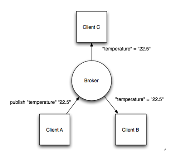
1. 訊息傳遞為Publish/Subscribe的方式,以提供一對多的訊息分派

  1. Client B及Client C先向Broker訂閱(Subscribe)一個Temperature主題, 而Client A向Broker發佈(Publish)在該主題Temperature發佈訊息(22.5),則Client B及Client C 都會收到此訊息。 
  1. 使用TCP port 1883作為通訊傳輸層 
  2.  Header固定長度為2 byte,因此可以減少封包傳送時的額外負載,並減少所需的網路頻寬 
  3. Publish 和Broker 中間發生異常斷線時,會使用最後遺囑(Last Will )的機制,通知所有Subscriber 
  4. 3種傳送服務QoS (0,1,2):
   Publisher <----> Broker <----> Subscriber
                  <QoS>           <QoS>

兩段所設定的QoS ,其作用的結果取兩段最小QoS值


1.)   QoS=0   "At most once": 最多送一次 ,但可能沒收到,"Fire and Forget"
      Publisher不會Re-Publish訊息給Broker。因為使用底層是TCP, 所以Broker 一定會收到,而剩下的問題為 Broker 和Subscriber 兩者間的傳輸問題。
      這適合應用在環境感測, Subscriber並不會在意Publisher是否會再重送,因為下一次的資料取樣很快就會再丟出來
2.)   QoS=1   "At least once": 可能收到一次以上 >=1
      如果時間內Publisher沒收到來自Broker的PUBACK, Publisher會Re-Publish訊息。如此Broker很有能收到2次以的重覆的訊息,因此Subscriber 就可能跟著會重覆收到相同訊息。
3.)   QoS=2   "Exactly once":只會收到一次=1
     為避免像QoS 1,  Subscriber有可能收到重覆的訊息。因此Publisher 會有Message ID, 使得Broker 能夠判別這是Publisher 所送的重覆資料, 才不致於送給Subscriber重複的資料。
      這適合用在計費系統,系統只要有重複收到資料、或是資料遺失狀況發生,就會造成系統錯誤。


CoAP vs MQTT 比較

  1. 都是公開標準且都是基於IP層的協定 
  2. 封包標頭小且採用binary格式 
  3. CoAP屬於一對一通訊,MQTT則是多對多 
  4. 若考慮感測節點在NAT後方的情況,由於MQTT的架構因為有中央broker的角色,MQTT Client本來就持續連接在broker,所以可以直接推播訊息,沒有NAT問題。然而CoAP Client要取得位於NAT後方的感測節點資料,則須要在路由器上設上設定virtual server或port forwarding之類才能使用,不然就必須另外有第三方伺服器存在,讓感測節點先連出才行


Raspberry Pico W 使用 MQTT publish


References:
  1. Observing Resources in the Constrained Application Protocol (CoAP)


https://goo.gl/EcCcj7