A botnet is a network of compromised computers or devices, often referred to as "bots" or "zombies," that are controlled remotely by a malicious actor (known as a "botmaster"). These devices are typically infected with malware, allowing the botmaster to execute various commands on them without the device owner’s knowledge.
Here are some common uses and dangers of botnets:
Distributed Denial of Service (DDoS) Attacks: Botnets are often used to flood a target server or website with traffic, overwhelming it and causing it to crash or become unavailable to users.
Spam Distribution: They can be used to send out massive amounts of spam emails or phishing messages, which can lead to further infections or fraud.
Credential Stuffing: Botnets may attempt to use stolen usernames and passwords on different sites, automating the process to try many combinations quickly.
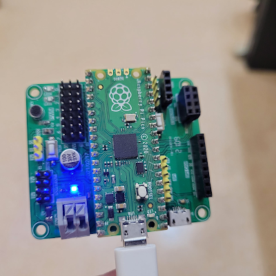
Raspberry Pi 基金會於 2021 年 1 月推出 Raspberry Pi Pico,正式進軍微控制器(MCU)領域。Pico 採用基金會自主設計的 RP2040 晶片,該晶片配備雙核 ARM Cortex-M0+(運行頻率最高可達 133MHz),內建 264KB SRAM 和 2MB Flash,其 GPIO 輸出為 3.3V。2024 年 11 月,基金會推出了 Raspberry Pi Pico 2 W 版本。其中「W」代表此版本內建 802.11n 無線網路功能,其核心晶片為 RP2350。
Pico 本身內建 bootloader,但不像 Raspberry Pi 或 Pi Zero 那樣運行 Linux 作業系統。為了方便開發,Raspberry Pi 基金會提供了 C/C++ SDK 和 MicroPython SDK。軟體和硬體與Raspberry Pi Pico 1相容。 Pico 也支援 TensorFlow Lite 框架,可用於開發輕量級的機器學習應用。
7 × 7 mm QFN-56 package
Raspberry Pi Pico 2的硬體規格:
雙Arm Cortex-M33或雙Hazard3處理器@150MHz
520 KB片上SRAM
2個UART。
2個SPI控制器。
2個I2C控制器。
24個PWM通道。
4個ADC通道。
1個USB 1.1控制器和PHY,支援主機和裝置。
12個PIO狀態機。
工作溫度-20°C至+85°C。
支援輸入電壓1.8–5.5V DC。
Raspberry Pi Pico
Pi Pico 擴充板規格
由於Raspberry Pi Pico 本身並未內建任何感應器,為了使其能夠應用於物聯網(IoT)及邊緣人工智能(Edge AI)等領域,特別採用了台灣程式教育協進會開發的 Pi Pico 擴充板。該擴充板的規格如下:
Pico + Pico 擴充板的一些物聯網應用
DEMO1
DEMO2
DEMO3
DEMO4
[課程]Raspberry Pi Pico 物聯網應用實作
https://bit.ly/4hTRptE
- 理解 Raspberry Pi Pico 硬體架構與擴充功能,並能運用 GPIO、ADC、PWM 等技術進行基礎硬體控制與感測應用。
- 熟悉 Thonny IDE 與 MicroPython 程式設計,具備多執行緒與時間控制能力。。
Since a single byte is normally used to define the slave address and each slave on a network requires a unique address, the number of slaves on a network is limited to 256. The limit defined in the modbus specification is even lower at 247.
master和slave之間走的Modbus 協定其封包格式有分ASCII 或RTU兩種
ASCII 為文字模式, 用character 傳送, RTU 為binary 模式傳送
封包格式: Slave ID | Function Code | Data | CRC
RTU 訊息格式
Information is stored in the Slave device in four different tables.
Two tables store on/off discrete values (coils) and two store numerical values (registers). The coils and registers each have a read-only table and read-write table.
Each table has 9999 values. Each coil or contact is 1 bit and assigned a data address between 0000 and 270E. Each register is 1 word = 16 bits = 2 bytes and also has data address between 0000 and 270E.
Coil/Register Numbers
Data Addresses
Type
Table Name
1-9999
0000 to 270E(9999)
Read-Write
Discrete Output Coils
10001-19999
0000 to 270E
Read-Only
Discrete Input Contacts
30001-39999
0000 to 270E
Read-Only
Analog Input Registers
40001-49999
0000 to 270E
Read-Write
Analog Output Holding Registers
Coil/Register Numbers can be thought of as location names since they do not appear in the actual messages. The Data Addresses are used in the messages.For example, the first Holding Register, number 40001, has the Data Address 0000. The difference between these two values is the offset.
Each table has a different offset. 1, 10001, 30001 and 40001.
What is a function code?
The second byte sent by the Master is the Function code. This number tells the slave which table to access and whether to read from or write to the table.
Function Code (Command) 3 is to read 4xxx registers, and 4 for 3xxx registers.
Function Code
Action
Table Name
01 (01 hex)
Read
Discrete Output Coils
05 (05 hex)
Write single
Discrete Output Coil
15 (0F hex)
Write multiple
Discrete Output Coils
02 (02 hex)
Read
Discrete Input Contacts
04 (04 hex)
Read
Analog Input Registers
03 (03 hex)
Read
Analog Output Holding Registers
06 (06 hex)
Write single
Analog Output Holding Register
16 (10 hex)
Write multiple
Analog Output Holding Registers
Example:
Read Holding Registers (FC=03)
Request
This command is requesting the content of analog output holding registers # 40108 to
40110 from the slave device with address 17. 11 03 006B 0003 7687 11: The Slave Address (11 hex = address17 ) 03: The Function Code 3 (read Analog Output Holding Registers) 006B: The Data Address of the first register requested.
( 006B hex = 107 , + 40001 offset = input #40108 ) 0003: The total number of registers requested. (read 3 registers 40108 to 40110) 7687: The CRC (cyclic redundancy check) for error checking. Response 11 03 06 AE41 5652 4340 49AD 11: The Slave Address (11 hex = address17 ) 03: The Function Code 3 (read Analog Output Holding Registers) 06: The number of data bytes to follow (3 registers x 2 bytes each = 6 bytes) AE41: The contents of register 40108 5652: The contents of register 40109 4340: The contents of register 40110 49AD: The CRC (cyclic redundancy check).
Read Coil Status (FC=01) Request
This command is requesting the ON/OFF status of discrete coils # 20 to 56
from the slave device with address 17. 11 01 0013 0025 0E84
11: The Slave Address (11 hex = address17 ) 01: The Function Code 1 (read Coil Status) 0013: The Data Address of the first coil to read.
( 0013 hex = 19 , + 1 offset = coil #20 ) 0025: The total number of coils requested. (25 hex = 37, inputs 20 to 56 ) 0E84: The CRC (cyclic redundancy check) for error checking. Response 11 01 05 CD6BB20E1B 45E6 11: The Slave Address (11 hex = address17 ) 01: The Function Code 1 (read Coil Status) 05: The number of data bytes to follow (37 Coils / 8 bits per byte = 5 bytes) CD: Coils 27 - 20 (1100 1101) 6B: Coils 35 - 28 (0110 1011) B2: Coils 43 - 36 (1011 0010) 0E: Coils 51 - 44 (0000 1110) 1B: 3 space holders & Coils 56 - 52 (0001 1011) 45E6: The CRC (cyclic redundancy check).
The more significant bits contain the higher coil variables. This shows that coil 36 is off (0) and 43 is on (1). Due to the number of coils requested, the last data field1Bcontains the status of only 5 coils. The three most significant bits in this data field are filled in with zeroes.
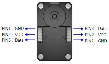
RS485 模組 (MAX485)的Pin 腳定義:
pin 1 :RO (receive out)
pin 2 RE (receive enable)
pin 3 :DE (data enable)
pin 4 :DI (data in)
pin 5, pin 8 : Gnd and Vcc onnected
pin 6,7 : A and B the RS485 pair
RO------->UART TX DI<------- UART RX 把/RE and DE 短路, 然後MCU/Pi 用一根GPIO 決定 /RE 或 DE.(即是決定是在送還是在收的狀態, 因為RS485是單工)